Wearable Heart Rate Monitoring Device Circuit Diagram
Wearable Heart Rate Monitoring Device Circuit Diagram Heart rate monitoring system by Rajendra Bhatt - An open-source heart rate monitoring system based on the photoplethysmography principle. How to connect the Raspberry Pi to a Bluetooth heart rate monitor by Clinton Freeman; Wiring the Heart Beat Sensor with Processing and Arduino - 14Core

While we progress with that, in this session, we will build a wearable Arduino heart rate monitor to measure the heart rate of a remote patient. Step 1: Components Required The following are the components required to build your Wearable Arduino based Heart Monitoring System In today's tutorial, we are going to design an IoT-based Heart Rate Monitoring System with ESP32 Microcontroller Board. Remote Health Monitoring Systems are evolving in the modern tech world because of their immense advantages, especially in rural areas where healthcare facilities are not readily available. Nowadays, these remote healthcare systems are even embedded in wearable devices to By leveraging a hub-based topology, developers can reduce the cost and complexity of managing and remotely logging data from multiple monitors. In this way, developers can design systems that meet the cost and reliability requirements of a variety of applications, from high-impact sports monitoring to critical patient heart monitoring in hospitals.
Designing a Wireless Heart Rate Monitor Circuit Diagram
managing and remotely logging data from multiple monitors. In this way, developers can design systems that meet the cost and reliability of a variety of applications, from high-impact sports monitoring to critical patient heart monitoring in hospitals. Cypress Semiconductor 198 Champion Court San Jose, CA 95134-1709 Phone: 408-943-2600

system to monitor patient's heart rate and blood oxygen concentration, with wireless notifications to a remote monitoring device. 1.3.2 Objectives of the Study

Wireless Open Source Heart Rate Monitors Circuit Diagram
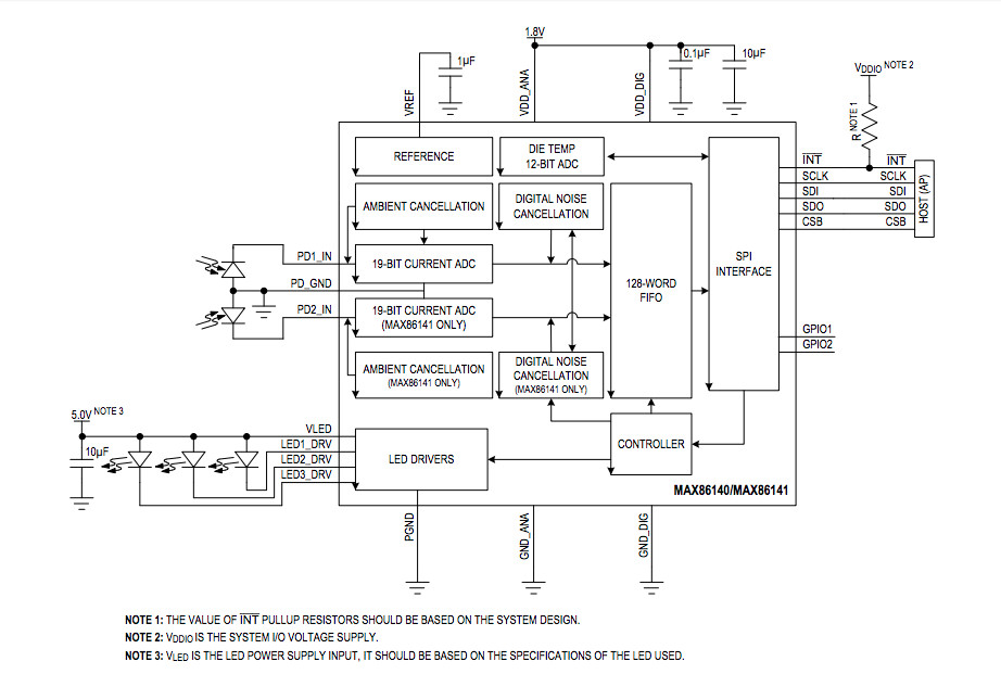
Heart Rate Monitoring System Overview The following block diagram shows the entire setup for the system. Some analog pins read faulty values when reading the sensor data while the board is connected to a Wi-Fi network because there can be conflicts between the ADC and the Wi-Fi on the ESP32.